Two-Beam Coupling
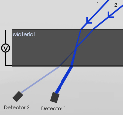
Two-beam coupling is the consequence of nonlocality of the photorefractive (PR) effect, i.e. non-zero phase shift (Φ). The experimental geometry is shown on the right. A typical sample consists of two conductive but transparent indium tin oxide (ITO)-coated glass slides with a PR organic (e.g. polymer composite) film of 30-100 μm thickness in between. Electric field is applied to the sample, and optical beams 1 (“probe” or “signal” and 2 (“pump” are incident and interfere in the PR material, creating a non-local diffraction grating. Then the same beams 1 and 2 partially diffract from the grating they have just created. Due to nonlocality of the grating, one diffracted beam interferes destructively with its companion beam 2, while the other diffracted beam interferes constructively with beam 1. As a result, the beam 1 is amplified (energy gain) while the beam 2 is attenuated (energy loss).
The period of the PR grating (Λ) is:
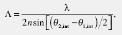
where λ is the wavelength, n is the refractive index, and θ1,int and θ2,int are internal angles of incidence of the beams 1 and 2 with respect to the sample normal, respectively.
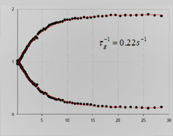
Typical data obtained in a two-beam coupling experiment is shown in figure below,O. Ostroverkhova et al., Appl. Phys. Lett. 82, 3602 (2003) which illustrates a change in light intensities of two beams transmitted through a PR sample as a function of time. In this case, beams of equal intensities are incident, and almost complete energy transfer occurs in several seconds.
Denoting beam 2 as the “pump”, the intensities of the transmitted “signal” beam (beam 1) (I1(out)) and of the “pump” beam (I2(out)) may be written as follows:
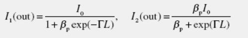
where the initial beam ratio (in the absence of coupling) is βp=I2(in)/I1(in), the total intensity I0=I1+I2, and the interaction length L=d/cosθint, where d is a sample thickness and θint is the internal angle between the beams. The two-beam coupling gain coefficient (Γ) is:
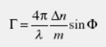
where λ is the wavelength, Δn is refractive index modulation, Φ is the phase shift, and m is the modulation depth (or contrast) of the interference pattern defined as m = 2 √(βp) / (1+βp). Clearly, if there is no phase shift, i.e. Φ = 0, then Γ = 0.
From the equations above, the gain coefficient Γcan be determined from experimentally measured intensities as follows: Γ=ln(βpI1(out)/I2(out))/L. Note that in the undepleted pump regime (βp >> 1), the gain factor γ0 defined as γ0=I1(out)/I1(in) simplifies to γ0=exp(ΓL), i.e. the intensity of the signal beam grows exponentially with the interaction length L. Two-beam coupling in this regime is used, for example, in image amplification.
The direction of energy transfer is determined by the sign of mobile charge carriers and of electro-optic response. Since most PR organic materials are poled in situ during the experiment, the sign of the electro-optic response depends on the applied electric field. Thus, the energy transfer direction can be reversed by changing the polarity of the electric field.